Sphere and cylindrical lens vertex power measurement with projection lensmeter
Introduction
Vertex power of the lens is usually measured in lensmeter. We distinguish some different types of lensmeters. Basic type is mechanical lensmeter with an eyepiece (eyepiece). Further we can use projection lensmeter or automated digital lensmeter.
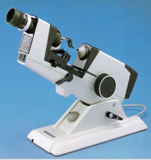
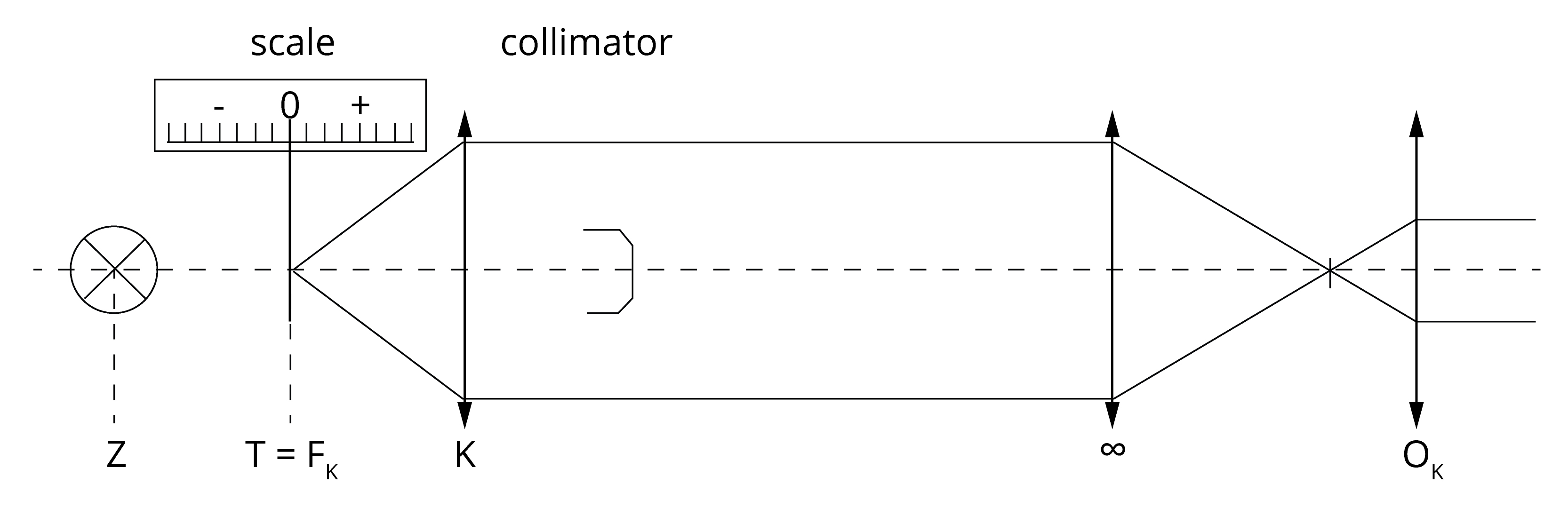
Mechanical lensmeter contains light source, collimator, rest peace for lens, holder for lens, marking device, objective and eyepiece with TABO-scheme.
Goals
- Individual adjustment of the lensmeter
- Measure total vertex power of the spherical lens
- Measure total vertex power of the cylindrical lens
Equipment
Mechanical lensmeter, spherical and cylindrical spectacle lens
Methods
Individual adjustment of the lensmeter
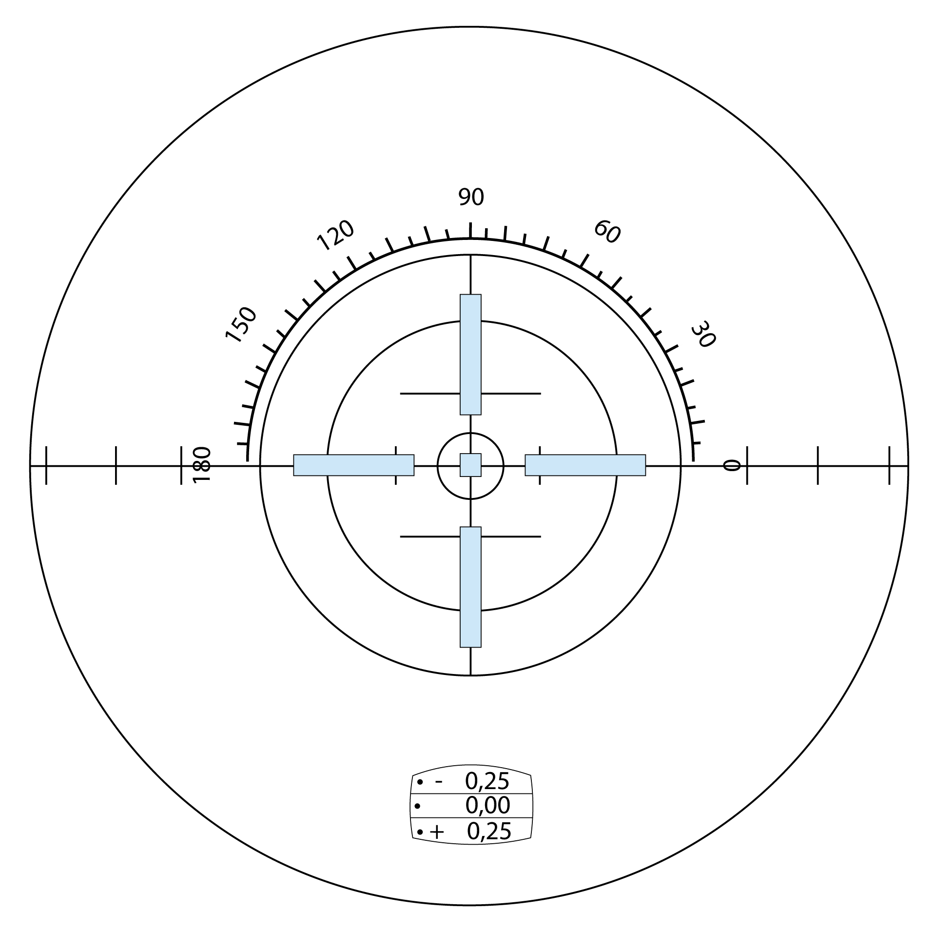
Before measurement of mechanical lensmeter you should adapt the eyepiece according the refraction status of the examiner. At first turn eyepiece counterclockwise as far as possible. After that turn with eyepiece clockwise until the TABO-scheme is clear. Further you should clear the green test mark. It should be clear when you can see zero on the scale.
Further you should check the exactness of the marking device of the lensmeter. At first draw two perpendicular lines on the lens. After that put the lens in lensmeter and mark it in 180 and 90 degrees. If these marks correspond with manual marking is the marking device correct.
Measure total vertex power of the spherical lens
Place the spherical lens in lensmeter. Concave side is down on the rest peace. With measuring screw turn into both sides to see the green test mark clearly. Finally write down the vertex power value rounded to 0.25 D.
Measure total vertex power of the cylindrical lens
Place the cylinder lens into lensmeter. Turn with measuring screw until the first principal meridian direction is clearly focused. Write down this cylindrical value rounded on 0.25 D and axis of this principal meridian with degrees (from 1 to 180).
Further we should measure second principal meridian which should differ in diopters and axis is rotated with 90 degrees.

Results
Individual adjustment of the lensmeter
Write down the number from eyepiece which you found during eyepiece adjustment. It can show you your eye refractive error.
Measure total vertex power of the spherical lens
SS =
Measure total vertex power of the cylindrical lens
SC1 =
Ax1 =
SC2 =
Ax2 =
Write sphero-cylindrical notation of cylindrical lens:
x sph comb. –y cyl ax. z deg.
x sph comb. +y cyl ax. z deg.
Discussion
Measurement on mechanical lensmeter needs examiner’s experience and practical skills. Firstly we start with lensmeter adjustment according refractive state of our eye. Here we can meet artificial accommodation (instrumental myopia) which can negatively influence measurement.
In practice there are many types of lensmeters. So, optician should meet the lensmeter and learn how the measure the lens. Majority of lensmeters have black TABO-scheme and green measuring mark. TABO-scheme is important for measuring axis of cylinder.
Conclusion, notes, comments
What is the refractive state after measurement on mechanical lensmeter?
Which eye is the leading eye?
What is the difference between cylindrical - cylindrical and sphero-cylindrical notation in spectacle lens?